3D Printer
Overview
Tinkerine Inc. is a leading 3D printer manufacturer based in Vancouver, Canada. I worked as a Firmware Engineer in the R&D department, where our team was responsible for developing the next generation of Fused Filament Fabrication (FFF) 3D printers.
In this role, I collaborated closely with electrical, mechanical, and software engineers to design and build the printer from the ground up.
This portfolio showcases highlights from our development process, carefully curated to respect the proprietary nature of the project while demonstrating the depth and impact of our work.
Concept Development
Design Requirements and Improvements
Our team focused on achieving the following objectives for the new design:
- Reliability: Ensure the system is more dependable, reducing errors and downtime.
- User-Friendliness: Simplify the user interface and interaction to make the product easier to operate for all users.
- Manufacturing Scalability: Design the product to streamline production processes, enabling efficient scaling of printer manufacturing to meet growing demand.
- Cost Efficiency: Maintain or reduce the cost of production without compromising on quality or functionality.
Technologies Implemented
To meet our design requirements, we selected and implemented the following technologies:
- Dual ARM Microcontrollers (Cortex M7):
- Utilized two separate ARM Cortex M7 microcontrollers for task distribution:
- One microcontroller handles user interface and control tasks, ensuring a responsive experience.
- The second microcontroller is dedicated to managing printing tasks, ensuring uninterrupted printing even while the user interface remains active.
- Utilized two separate ARM Cortex M7 microcontrollers for task distribution:
- Touchscreen LCD:
- Integrated a touchscreen LCD for a more intuitive and user-friendly interaction, enhancing the overall user experience.
- USB A and USB B Ports:
- USB A: Allows users to connect USB flash drives directly to the printer for easy file transfers.
- USB B: Facilitates direct connection to a computer for data transfer and printer control.
- Ethernet and Wi-Fi Connectivity:
- Provided both Ethernet and Wi-Fi options for seamless internet connectivity, enabling remote monitoring and updates.
- Semi-Automatic Bed Leveling (using Accelerometer):
- Implemented semi-automatic bed leveling using an accelerometer to enhance print quality by ensuring the print bed is correctly calibrated.
- Filament Detection (using Encoder):
- Incorporated a filament detection system utilizing an encoder to monitor filament usage and prevent print failures due to filament run-out.
Microcontroller Selection
Selecting the right microcontrollers was a critical decision in the design process, as it directly impacted the performance, scalability, and reliability of the new printer.
The older generation printers were Arduino-based, utilizing Atmel’s Atmega 2560 processor (8-bit AVR, 16 MHz, 8 KB SRAM). For the newer generation, we sought to upgrade to modern 32-bit ARM microcontrollers that offered a rich set of built-in peripherals to streamline design and functionality.
We evaluated microcontrollers from several leading silicon manufacturers, including Atmel, Freescale, NXP, and STMicroelectronics. The STM32 series from STMicroelectronics emerged as the best choice, offering the ideal combination of peripherals, performance, and support.
To meet our requirements for long-term availability, quick procurement, and stable pricing, we selected the STM32F746 for both microcontrollers. Key features of the STM32F746 include:
- High Performance: Capable of running at up to 216 MHz.
- Large Memory: 512 KB of built-in SRAM to handle complex tasks efficiently.
- Direct Memory Access (DMA): Includes DMA and DMA2D for efficient data transfers without processor intervention, enhancing system performance.
- Extensive Built-in Peripherals: Features like an LCD controller, USB OTG (supporting both USB host and device modes), timers, DSP (Digital Signal Processing), and more, reducing the need for additional external components and simplifying the design process.
This choice ensured that our new design could meet modern performance standards while maintaining reliability and cost-effectiveness.
System Overview
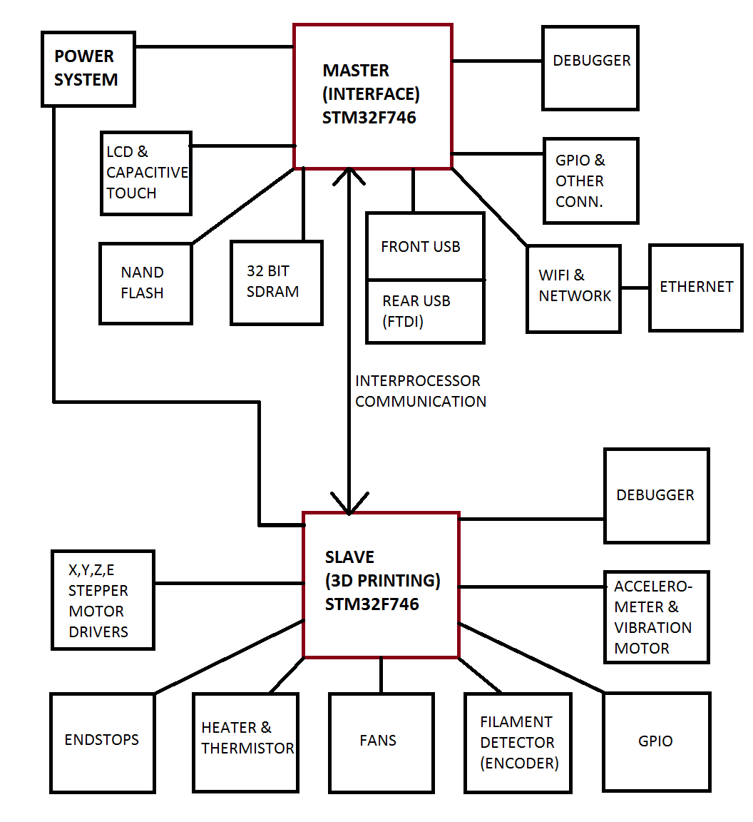
With the microcontrollers selected, we developed a high-level system architecture to guide the overall design. This allowed us to identify and choose the additional components necessary to complete the system, ensuring all elements integrated seamlessly to meet performance and reliability goals.

System Components
In addition to standard printer hardware such as motors, heaters, and fans, we selected the following components to enhance the functionality and performance of the system:
- 24-bit RGB Touchscreen LCD:
- Features 24 data lines and an I2C interface for touchscreen functionality, providing a vibrant and interactive user interface.
- 32-bit SDRAM:
- Used to store LCD frame buffers and other data, ensuring smooth graphical performance and efficient memory management.
- 4GB eMMC NAND Flash:
- Provides reliable storage for user files and essential printer files.
- SPI Wi-Fi Module with RMII Interface:
- Enables wireless connectivity alongside Ethernet for versatile internet access.
- I2C Accelerometer:
- Supports semi-automatic bed leveling and vibration monitoring to improve print quality.
- FTDI UART to USB IC:
- Facilitates efficient communication between the system and external USB devices.
System Architecture
To optimize performance and user experience, we distributed components between the two microcontrollers as follows:
-
Master Microcontroller (User Experience):
- Connected to the touchscreen LCD, USB A and USB B ports, Wi-Fi, and Ethernet.
- Paired with external SDRAM and NAND flash to enhance memory capacity and storage, enabling a seamless and responsive user interface.
-
Secondary Microcontroller (Printing Functions):
- Responsible for managing critical printing hardware, including heaters, thermistors, stepper motors, fans, filament detector, accelerometer, and a vibration motor.
- Dedicated to ensuring precise and uninterrupted printing performance.
Firmware Architecture
The core of any 3D printer’s performance lies in its print quality. Without reliable and precise outputs, even the most advanced features are rendered insignificant. Guaranteeing consistent execution times for critical processes is paramount; delays of even a few milliseconds can result in failed prints or undesirable artifacts.
To ensure deterministic execution for critical tasks, I employed a Real-Time Operating System (RTOS), selecting FreeRTOS, an open-source solution distributed under the MIT license.
Modular Design for Robustness and Scalability
The firmware architecture is built around a modular design principle:
- All tasks, aside from interrupt service routines (ISRs) and the FreeRTOS task scheduler, are executed within independent processes managed by FreeRTOS.
- Each peripheral or feature is implemented as a separate process, simplifying development, debugging, and troubleshooting.
- Fault isolation is inherent to this design. If a process or feature encounters an issue, it does not compromise the entire system. The faulty process can be restarted, and dependent processes can either halt or terminate gracefully before recovery.
System Initialization
- Upon power-up, the processor executes the startup code, which:
- Performs diagnostic tests to ensure system integrity.
- Configures the processor to its initial state, preparing it to initialize the RTOS.
- Once the RTOS is running, essential processes—such as graphics, networking, and other core functions—are created. These processes can dynamically spawn child processes as needed, adding flexibility to the system architecture.
Interrupt Service Routines (ISRs)
ISRs are designed as blocking functions, meaning they halt other tasks until their execution is complete. To ensure that critical processes are not delayed:
- Minimized Execution Time: ISRs handle only time-critical operations, such as reading and writing to processor and peripheral registers, and controlling the motors.
- Deferred Processing: Non-urgent data is stored and passed to a process for later handling.
- Scheduler Integration: After completing its tasks, the ISR returns control to the RTOS scheduler, which executes the process with the highest priority, ensuring seamless task management and uninterrupted performance.
By leveraging FreeRTOS and adhering to a modular design with optimized ISR management, the firmware architecture ensures high reliability, maintainability, and superior print quality.
Firmware for Master MCU
The master microcontroller serves a dual purpose: it handles the user experience (UX) and communicates with the slave processor by sending G-code via UART.
A significant portion of the firmware development took place on STM32 development kits, which allowed us to test individual modules while the PCB layout and manufacturing were in progress. This approach enabled independent testing of key components and features before fully integrating them into the final system, ensuring each module functioned correctly prior to assembly.
This method of development provided a more efficient workflow, reduced potential integration issues, and accelerated the overall development timeline.
SDRAM and NAND flash
I developed custom drivers to support the 32-bit SDRAM connected to the master MCU. The drivers were responsible for programming the MCU registers to the appropriate values, as well as sending the necessary commands to the SDRAM for configuration, data reading, and writing.
In addition, I wrote custom drivers for the eMMC NAND flash since no suitable pre-existing drivers were available at the time. These drivers facilitated seamless interaction with the NAND flash for storage, ensuring reliable performance in data management.
File System
To enable file read/write functionality on the internal storage and USB flash drives, we implemented support for the FAT file system. Initially, I experimented with FreeRTOS + FAT (a FAT FS by FreeRTOS), but ultimately chose FatFS by elm-chan for its reliability and performance.
I developed supporting functions to read and write data blocks to both NAND flash and USB drives. To ensure robust concurrent access, I made these functions thread-safe, allowing multiple threads to read/write simultaneously without conflict.
Additionally, the printer automatically checks the NAND flash for a file system configuration; if none exists, it initializes and creates one on the fly.
Touchscreen LCD
The first step in implementing graphics was to determine the memory requirements. I calculated the necessary memory for loading assets and supporting two frame buffers for double buffering. This calculation was critical for selecting the appropriate SDRAM size. In parallel, I conducted performance testing to ensure the STM32F7 processors could maintain a consistent frame rate, especially when rendering animations.
Since the manufacturer did not provide touchscreen drivers, I developed custom drivers for the touchscreen. Using I2C, I read the touch input data and passed it to the graphics library for processing.
Below is a video demonstrating the Mandelbrot Set running on the development kit. This showcases the performance and capabilities of the system, particularly how well the STM32F7 handles complex graphical computations and rendering in real-time.
While several graphics libraries were available for embedded systems, I chose STemWin, a free library provided by STMicroelectronics based on the Segger emWin graphics library. I customized some functions in the ST driver for STemWin to better suit our hardware, and also wrote additional functions to integrate STemWin with FreeRTOS.
The user interface (UI) design was handled by another team member, and once I received the design and assets, I used STemWin to implement the UI. The final system featured approximately 25 unique screens, including images, gifs, textboxes, buttons, keyboards, and navigation elements.
USB
To enable connection with USB flash drives, we implemented USB A support. The provided drivers and USB host stack from ST were too large and relied on outdated HAL drivers that were incompatible with our project. To resolve this, I referred to the USB specifications from USB-IF and developed a custom mini USB host driver with mass storage device support, allowing the printer to read and write to USB drives.
For connecting the printer to computers, we added USB B support. Using a UART to USB chip with the master microcontroller, I developed a module to send and receive data and commands between the printer and the computer.
Wi-Fi and Ethernet
Wi-Fi and Ethernet connectivity were implemented using a hardware module that communicated with the master MCU via UART. The module manufacturer provided the necessary functions for communication, and I developed a software module to send commands and receive data from the hardware module, ensuring seamless integration of networking capabilities into the printer.
Firmware for Slave MCU
The slave processor was dedicated to handling the printing tasks. It received G-code from the master processor, decoded the commands, and executed the necessary printing operations. Communication between the master and slave processors was facilitated via UART.
Heater, Thermistor and PID
The print head was one of the most sensitive components, requiring precise temperature control for consistent print quality. To achieve this, I used a GPIO pin to control the heater via a MOSFET, ensuring precise switching. The MCU’s ADC was used to measure the nozzle temperature through a thermistor.
To maintain the optimal temperature, I implemented a PID control algorithm. This allowed the system to turn the heater on and off at the right moments, ensuring that the temperature remained stable and within the required range throughout the printing process.
Stepper Motors
Stepper motors were used to control the movement of the print head and the bed. I developed modules to manage the acceleration and deceleration of the motors, incorporating timer functions and interrupt handlers for high precision control. To optimize performance, I used DMA (Direct Memory Access) wherever possible, reducing interrupt load and ensuring smoother motion during the printing process.
G-code and look-ahead
The G-code decoder was one of the largest modules I developed for the slave MCU. While not the most complex, it was sizable due to the need to process plain text G-code commands. Some commands were executed immediately, while others were queued for later execution. When it came time to execute, the module would read the command and call the appropriate function.
The most challenging and interesting part was the look-ahead functionality. The module would analyze a few future commands to predict and generate a trajectory, allowing the system to calculate the necessary motor speed. This approach ensured smooth transitions between commands, reducing interruptions and enabling faster, smoother prints.
Acclerometer
An accelerometer connected via I2C was used to detect various motions. I developed the drivers to configure the accelerometer to the correct mode and read the acceleration data. To ensure accurate readings, I applied digital signal processing (DSP) techniques to clean the data.
The accelerometer was utilized in PID control for the print head and worked in conjunction with a vibration motor to provide semi-automated bed leveling, improving print quality and consistency.
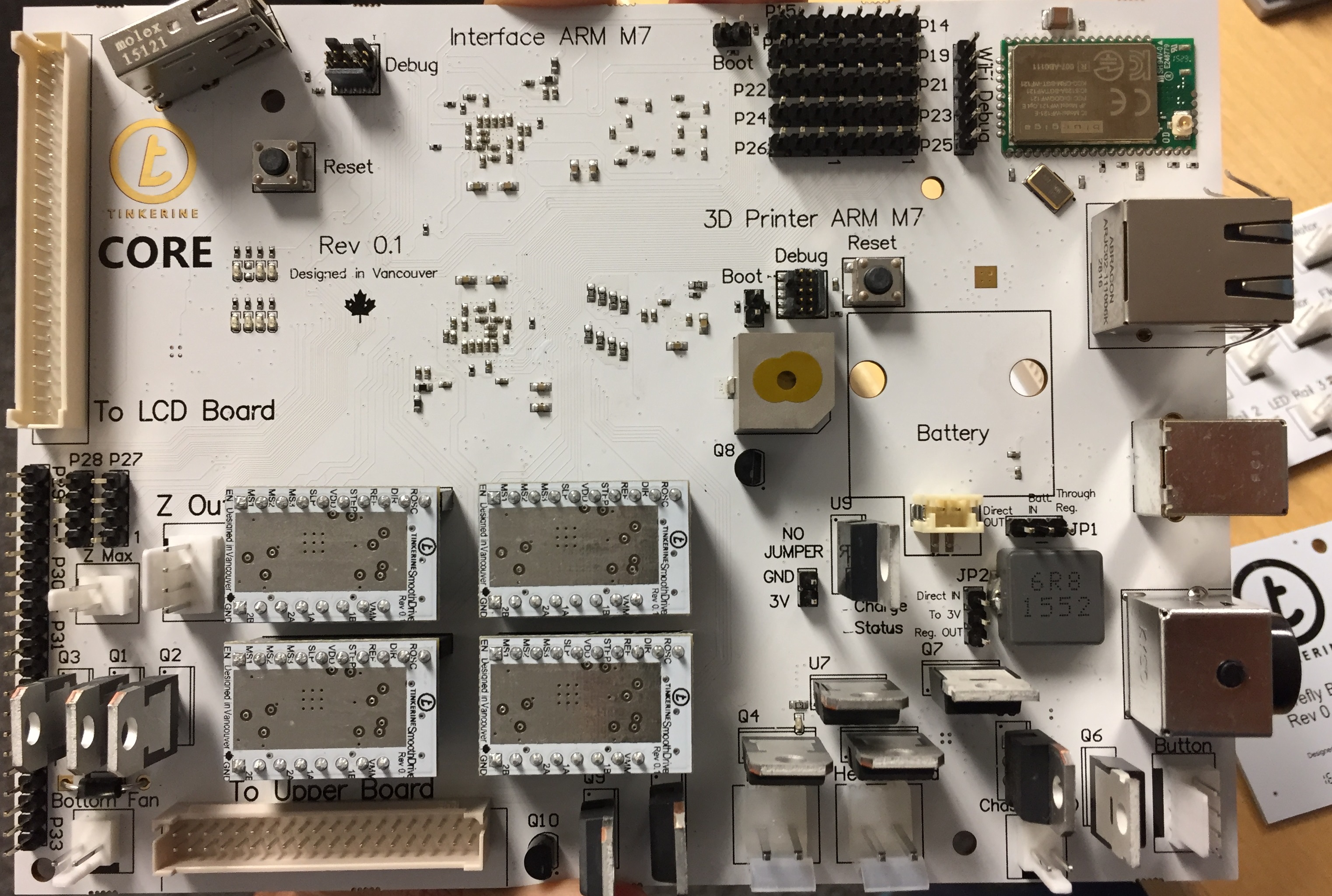
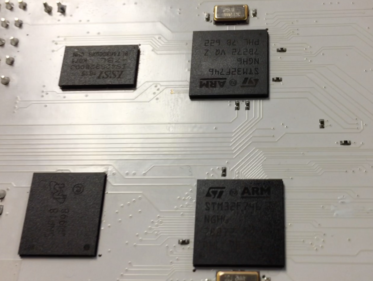
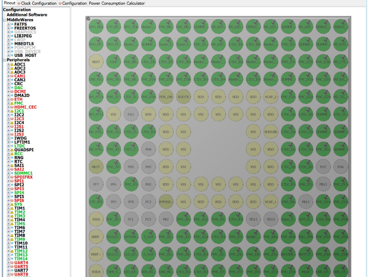
Pictures of hardware and pinouts


